circuit board components identification pdf
Welcome to our guide on circuit board components identification. This essential resource helps you recognize and understand PCB elements‚ ensuring accurate troubleshooting and efficient repairs through visual inspection‚ reference designators‚ and advanced techniques.
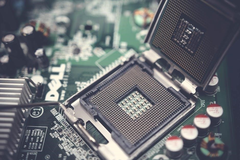
Overview of Printed Circuit Boards (PCBs)
Printed Circuit Boards (PCBs) are the backbone of modern electronics‚ serving as the platform for connecting and powering electronic components. A PCB consists of a conductive material‚ typically copper‚ etched onto a non-conductive substrate‚ such as fiberglass or plastic. This design enables the creation of complex electrical pathways and connections between components like resistors‚ capacitors‚ and integrated circuits. PCBs are fabricated using advanced manufacturing techniques‚ ensuring precision and reliability. They are widely used in devices ranging from simple toys to sophisticated computers. The compact and organized nature of PCBs minimizes wiring errors and enhances device performance; Understanding PCB construction is crucial for component identification and efficient troubleshooting in electronic systems.
Importance of Component Identification in PCB Design
Accurate component identification is critical in PCB design to ensure functionality‚ reliability‚ and safety. Each component plays a specific role‚ and misidentification can lead to circuit malfunctions or even device failure. Proper identification aids in troubleshooting‚ enabling engineers to pinpoint and rectify issues efficiently. It also facilitates effective communication among design teams‚ ensuring consistency and reducing errors. Additionally‚ component identification is vital for compliance with industry standards and regulations. By understanding and labeling each part correctly‚ designers can optimize performance‚ minimize risks‚ and streamline the manufacturing process. This step is foundational for creating robust and dependable electronic systems‚ making it an indispensable skill in PCB design and development.
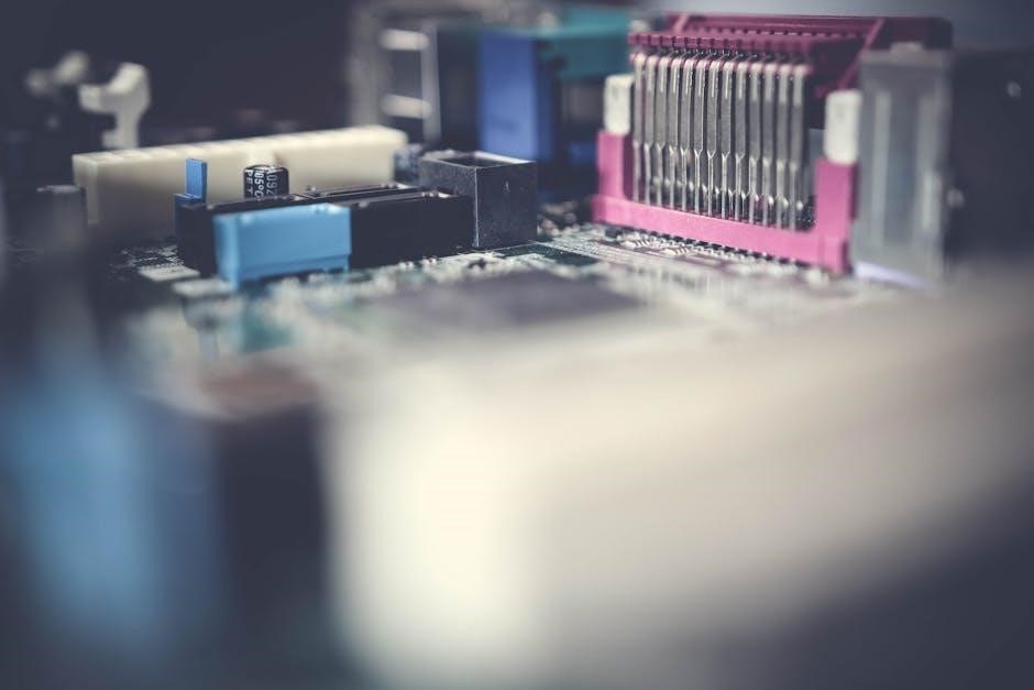
Common Circuit Board Components
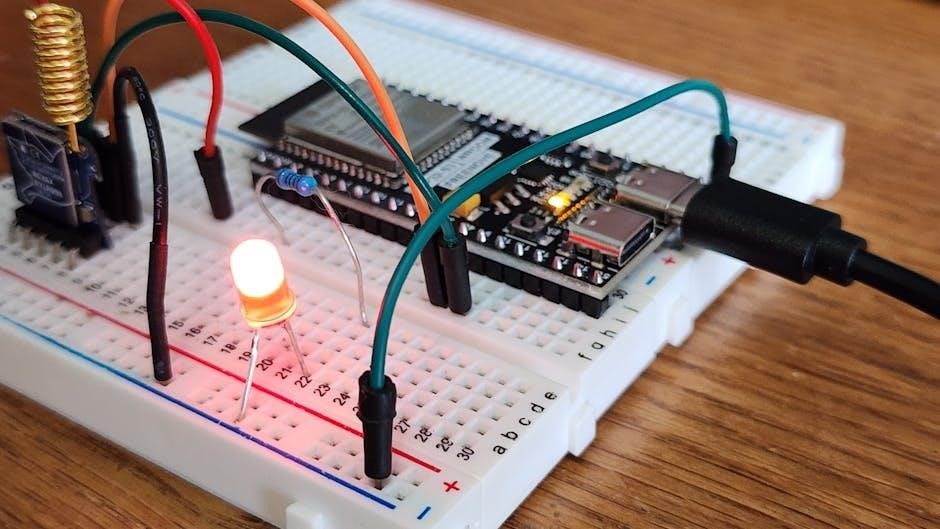
Circuit boards feature essential components like resistors‚ capacitors‚ diodes‚ transistors‚ and integrated circuits (ICs). These elements‚ in both through-hole and surface-mount technologies‚ play vital roles in enabling electronic systems.
Resistors: Identification and Specifications
Resistors are among the most common components on a circuit board‚ functioning to reduce voltage or limit current. They are typically cylindrical or rectangular‚ with color-coded bands indicating their resistance in ohms. The number of bands varies‚ but standard resistors often have four or five‚ representing significant digits‚ a multiplier‚ and tolerance. Fixed resistors have set values‚ while variable resistors (potentiometers) allow adjustment. Specifications include power rating‚ tolerance‚ and temperature coefficient. Identification involves matching the color codes to a resistor chart or using a multimeter for precise measurement. Proper recognition ensures correct circuit operation and avoids damage from mismatched components.
- Color coding is the primary method for resistor identification.
- Specifications include resistance value‚ power rating‚ and tolerance.
- They are essential for voltage division‚ signal attenuation‚ and circuit protection.
Capacitors: Types and Identification Techniques
Capacitors are essential components used to store electrical energy and filter signals in circuits. They come in various types‚ including ceramic‚ electrolytic‚ film‚ and tantalum‚ each with distinct characteristics. Ceramic capacitors are small‚ non-polarized‚ and commonly used for high-frequency applications. Electrolytic capacitors are larger‚ polarized‚ and suitable for filtering and energy storage. Identification involves checking the casing for voltage ratings‚ capacitance values (often in microfarads)‚ and polarity markings. Tantalum capacitors are recognizable by their distinctive shape‚ while film capacitors are known for stability and low inductance. Using a multimeter or referencing the component’s datasheet ensures accurate identification‚ crucial for maintaining circuit functionality and preventing damage from incorrect installation.
- Ceramic capacitors are non-polarized and ideal for high-frequency use.
- Electrolytic capacitors have polarity and are used for filtering.
- Capacitance values are often marked in microfarads (µF) or nanofarads (nF).
Diodes: Recognition and Functionality
Diodes are fundamental components in electronic circuits‚ functioning as one-way switches for current flow. They are easily recognizable by their distinct shape‚ typically featuring two terminals with a band or marking indicating the cathode side. Reference designators like “D” or “CR” often label diodes on PCBs. Common types include rectifier diodes for AC-to-DC conversion‚ schottky diodes for low-voltage drops‚ zener diodes for voltage regulation‚ and LEDs for light emission. Diodes are crucial for applications like rectification‚ signal demodulation‚ and voltage protection. Identifying diodes involves checking their physical appearance‚ reference labels‚ and voltage ratings. Proper functionality ensures efficient current flow and circuit protection‚ making accurate identification essential for troubleshooting and repair.
- Diodes allow current flow in one direction and block it in the other.
- They are identified by their shape and cathode markings.
- Key types include rectifier‚ schottky‚ zener‚ and LED diodes.
Transistors: Identification and Application
Transistors are key semiconductor devices used to amplify or switch electronic signals. They are easily identifiable by their three terminals: base‚ collector‚ and emitter. Reference designators like “Q” or “T” often label transistors on PCBs. Transistors come in two main types: bipolar junction transistors (BJTs) and field-effect transistors (FETs). BJTs rely on current flow between collector and emitter‚ controlled by the base‚ while FETs use voltage to create a conductive channel. Common applications include audio amplifiers‚ switching circuits‚ and voltage regulation. Identifying transistors involves checking their physical shape‚ terminal layout‚ and reference labels. Proper functionality ensures efficient signal control‚ making accurate identification crucial for circuit performance and troubleshooting.
- Transistors act as amplifiers or switches in electronic circuits.
- They are recognized by their three-terminal structure.
- Types include BJTs and FETs‚ each with unique functionalities.
Integrated Circuits (ICs): Pin Configuration and Identification
Integrated Circuits (ICs) are complex semiconductor devices containing multiple electronic components within a single package. Identifying ICs involves understanding their pin configurations‚ which vary by type and function. Common ICs include voltage regulators‚ operational amplifiers‚ and microcontrollers. Reference designators like “U” or “IC” label these components on PCBs. Pins are numbered sequentially‚ with polarity and function detailed in datasheets. Proper identification ensures correct installation and functionality. Key steps include examining the package type (e.g.‚ DIP‚ SOP‚ or QFP)‚ checking the manufacturer’s markings‚ and referencing the datasheet for pin assignments. Accurate identification is critical for troubleshooting and ensuring optimal circuit performance.
- ICs are compact packages with multiple internal components.
- Pin configurations are detailed in datasheets for proper functionality.
- Common ICs include voltage regulators and microcontrollers.
Component Identification Techniques
Effective component identification involves visual inspection‚ reference designators‚ and automated tools. These methods ensure accuracy in recognizing and troubleshooting PCB elements efficiently.
- Visual inspection identifies shapes‚ colors‚ and markings.
- Reference designators provide component labels for easy lookup.
- Automated tools enhance precision and speed in identification.
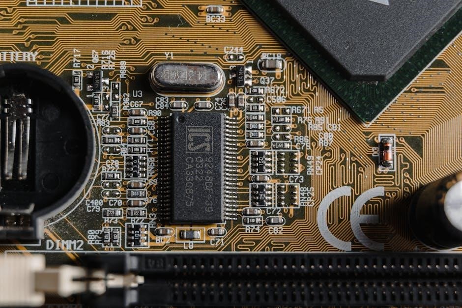
Visual Inspection: Shapes‚ Colors‚ and Markings
Visual inspection is a fundamental technique for identifying circuit board components. By examining the shape‚ color‚ and markings‚ technicians can determine the type and specifications of each part. Resistors‚ for instance‚ are often rectangular with color bands indicating their resistance values. Capacitors may appear cylindrical or rectangular‚ with markings showing capacitance and voltage ratings. Diodes are recognizable by their distinctive arrow symbols‚ while transistors often feature three terminals. Polarized components‚ such as electrolytic capacitors‚ have clear polarity indicators. Using magnifying tools‚ especially for surface-mount components‚ enhances accuracy. This method is crucial for detecting physical damage or incorrect placement‚ ensuring reliable PCB troubleshooting and maintenance.
Reference Designators: Understanding Component Labels
Reference designators are standardized labels assigned to components on a circuit board‚ ensuring clarity and consistency in identification. These labels typically consist of a letter prefix indicating the component type (e.g.‚ “R” for resistors‚ “C” for capacitors‚ and “Q” for transistors) followed by a numerical suffix. For instance‚ “R1” denotes the first resistor‚ while “IC1” identifies the first integrated circuit. These designators are essential for mapping components during PCB assembly‚ troubleshooting‚ and repair. They also align with schematic diagrams‚ making it easier to trace connections and verify functionality. Accurate reference designators are critical for efficient documentation and communication among engineers and technicians working on the board. This system ensures that every component is uniquely identifiable‚ streamlining the entire design and maintenance process.
Automated Identification: OCR and AI Solutions
Automated identification techniques like OCR (Optical Character Recognition) and AI solutions revolutionize circuit board component identification. OCR enables quick recognition of text on components‚ such as labels and markings‚ enhancing accuracy in identifying parts. AI-powered tools analyze visual data from PCBs‚ detecting patterns and features to classify components. These technologies are particularly useful for complex or densely populated boards‚ where manual inspection is time-consuming. AI-driven systems can learn from datasets to improve recognition accuracy‚ reducing human error. Advanced solutions combine OCR with AI for comprehensive component analysis‚ offering real-time data and improving efficiency in manufacturing and repair. By integrating these technologies‚ industries achieve faster and more reliable component identification‚ enabling smart manufacturing and data-driven traceability.
Tools and Resources for Component Identification
Essential tools include multimeters‚ component testers‚ and magnifying tools for precise inspection. Online databases and specialized software provide detailed component information‚ enhancing identification accuracy and efficiency.
Component Testers: How to Use Them Effectively
Component testers are essential tools for verifying the specifications and functionality of electronic components. They can quickly identify resistors‚ capacitors‚ transistors‚ and other elements. To use them effectively‚ start by selecting the correct test mode based on the component type. For resistors‚ measure resistance; for capacitors‚ check capacitance and ESR. Transistors can be tested for gain and polarity. Diodes can be verified for forward voltage drop. Always ensure the tester is calibrated and use the proper test leads. For complex components like ICs‚ use advanced testers with preset test profiles. Regularly update your tester’s firmware for accurate results. These tools save time and improve repair accuracy‚ making them indispensable for PCB troubleshooting and maintenance.
Online Databases and Catalogs for Component Lookup
Online databases and catalogs are invaluable resources for identifying and verifying circuit board components. Platforms like Digi-Key‚ Mouser‚ and Chipdip.ru provide extensive libraries of components‚ complete with datasheets‚ specifications‚ and images. Engineers and technicians can search by part number‚ description‚ or even visual appearance. These tools often include advanced filters to narrow down results based on parameters like voltage‚ current‚ or package type. Many databases also offer cross-referencing features to find compatible or alternative parts. Additionally‚ some platforms provide 3D models for visualizing components in PCB designs. Regular updates ensure access to the latest components. Using these resources streamlines the identification process‚ reducing errors and enhancing efficiency in PCB design and repair.
Specialized Tools for PCB Analysis
Specialized tools for PCB analysis are essential for efficiently identifying and testing components. Automated traceability solutions‚ such as OCR and AI-powered systems‚ enable quick and accurate component recognition. These tools can decode markings‚ even when they are faded or damaged. Additionally‚ smart manufacturing technologies integrate data-driven tracking‚ providing real-time insights into component performance and location. Advanced devices‚ like component testers‚ offer detailed diagnostics for resistors‚ capacitors‚ and ICs. Some innovators‚ such as Chris‚ have developed unique tools to simplify component identification. These resources enhance precision‚ reduce errors‚ and streamline PCB repair processes. By leveraging these tools‚ engineers and technicians can ensure reliable and efficient circuit board maintenance and troubleshooting.
Troubleshooting and Replacing Components
Identifying faulty components involves visual inspection and testing. Replacement requires precise soldering and desoldering techniques. Adhering to best practices ensures reliable PCB repair and optimal functionality restoration.
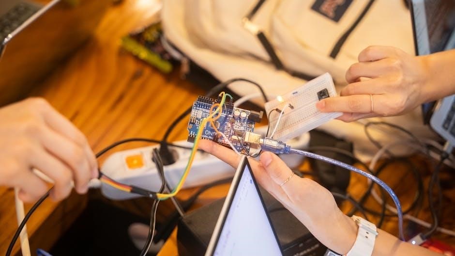
Step-by-Step Guide to Identifying Faulty Components
Start with a visual inspection to spot physical damage‚ such as burn marks‚ discoloration‚ or cracks. Use a multimeter to test voltage‚ current‚ and resistance‚ ensuring safe connections without causing further damage. Refer to component designators (e.g.‚ R1‚ C3) to match with parts lists or datasheets for identification. Employ component testers for automatic identification and testing if available. Isolate components to test individually‚ ensuring the board is powered off and safe. Ground yourself to prevent static damage. After identifying faults‚ replace components with precise soldering‚ then retest the board to confirm functionality. Systematically check each part‚ and consider practicing soldering on spare boards to build confidence and skill.
Replacement Techniques: Soldering and Desoldering
Mastering soldering and desoldering is crucial for replacing faulty components on a circuit board. For soldering‚ apply a small amount of solder to the tip of your iron‚ heat the component lead and pad simultaneously‚ then flow the solder evenly. Use a soldering iron with an appropriate temperature (around 350°C) to avoid damaging components or the PCB. Desoldering requires a desoldering pump or wick to remove excess solder safely. Heat the joint‚ then use the wick to absorb the melted solder. Ensure the board is grounded to prevent static damage. Practice on scrap boards to refine your technique‚ and always use flux to improve solder flow. Proper soldering ensures reliable connections‚ while careful desoldering prevents PCB damage.
Best Practices for PCB Repair and Maintenance
Adhering to best practices is essential for effective PCB repair and maintenance. Always ground yourself to prevent static discharge‚ which can damage sensitive components. Use high-quality tools‚ such as precision screwdrivers and soldering irons‚ to ensure accurate repairs. Clean the board thoroughly with isopropyl alcohol to remove dirt and residue. Document all repairs for future reference. Test the board after each repair to verify functionality. Store PCBs in a dry‚ cool environment to prevent corrosion. Regularly inspect for signs of wear‚ such as cracked solder joints or discolored components. Avoid overheating components during soldering to prevent damage. By following these practices‚ you can extend the lifespan of your PCB and maintain its reliability.
Advanced Topics in Component Identification
Explore advanced techniques‚ including polarized component orientation‚ SMT vs. through-hole differences‚ and passive vs. active classification‚ to enhance your PCB design and functionality expertise.
Polarized Components: Identification and Orientation
Polarized components‚ such as capacitors and diodes‚ require correct orientation to function properly. Identification often involves visual cues like stripes‚ arrows‚ or plus signs. For capacitors‚ the longer leg indicates the positive terminal‚ while for diodes‚ the cathode is marked with a stripe. Incorrect orientation can lead to component failure or damage. Always refer to the datasheet for specific polarity requirements. Proper installation ensures circuit reliability and safety. Using automated tools or visual aids can help confirm correct placement during PCB assembly;
Surface-Mount Technology (SMT) vs. Through-Hole Components
Surface-Mount Technology (SMT) components are mounted directly onto the PCB surface‚ offering smaller sizes and higher density‚ while Through-Hole components use leads inserted into board holes. SMT is ideal for compact‚ high-volume applications due to its space-saving design and automated assembly efficiency. Through-Hole components provide stronger mechanical connections and are often used in high-reliability or prototyping scenarios. SMT components are generally cheaper for mass production but require specialized soldering tools. Through-Hole parts are easier to hand-solder‚ making them suitable for DIY projects. Understanding these differences is crucial for selecting the right components based on application needs‚ ensuring optimal performance and cost-effectiveness in PCB design and manufacturing.
Classifying Components: Passive vs. Active Elements
Components on a circuit board can be categorized into passive and active elements. Passive components‚ such as resistors‚ capacitors‚ and inductors‚ do not require an external power source to operate. They store‚ dissipate‚ or transfer energy without amplifying signals. Active components‚ including transistors‚ diodes‚ and integrated circuits (ICs)‚ require a power source to function and can amplify or modify electrical signals. This classification is essential for understanding PCB design and functionality. Passive components are simpler‚ while active components enable complex operations like signal processing and amplification. Proper identification and classification ensure efficient circuit operation‚ troubleshooting‚ and repair‚ making this distinction fundamental in electronics engineering and PCB analysis.

Future Trends in Circuit Board Component Identification
Future trends include AI-driven component recognition tools‚ automated traceability solutions‚ and smart manufacturing technologies‚ enhancing PCB design‚ tracking‚ and maintenance efficiency through advanced data-driven systems and real-time analytics.
Automated Traceability Solutions for PCBs
Automated traceability solutions are revolutionizing PCB component identification by enhancing accuracy and speed. These systems utilize advanced OCR and AI technologies to scan and recognize components swiftly. By integrating with smart manufacturing processes‚ they provide real-time data analytics‚ enabling seamless tracking of components across the production lifecycle. Such solutions improve supply chain transparency and reduce errors in component identification. They also support predictive maintenance by monitoring component health and performance. With automated traceability‚ manufacturers can ensure compliance with quality standards and optimize inventory management. These innovations are critical for scaling production while maintaining precision and reliability in modern electronics manufacturing. They represent a significant leap forward in PCB design and maintenance efficiency.
Smart Manufacturing and Data-Driven Component Tracking
Smart manufacturing integrates advanced technologies like IoT‚ AI‚ and machine learning to enhance PCB component tracking. By leveraging real-time data‚ manufacturers can monitor components throughout the production lifecycle‚ ensuring precision and transparency. Data-driven systems enable predictive analytics‚ helping to identify potential component failures before they occur. This approach optimizes inventory management and reduces production downtime. Automated solutions also improve traceability‚ allowing for faster identification of components and their origins. Smart manufacturing fosters collaboration between systems‚ creating a seamless workflow for PCB assembly and repair. By adopting these technologies‚ manufacturers can achieve higher efficiency‚ reduce errors‚ and maintain consistent quality in electronic devices. This data-centric approach is reshaping the future of PCB design and production.