3-way dimmer switch wiring diagram pdf
A 3-way dimmer switch allows control of lighting brightness from multiple locations‚ enhancing convenience and energy efficiency. It seamlessly integrates with existing wiring systems‚ offering smooth dimming functionality for various lighting setups.
What is a 3-Way Dimmer Switch?
A 3-way dimmer switch is an electrical device designed to control the brightness of lighting fixtures from two different locations. Unlike a standard dimmer‚ which operates a single light source‚ a 3-way dimmer works in tandem with a second switch‚ allowing seamless control of the same light from multiple points. This setup is particularly useful in larger spaces‚ such as hallways or staircases‚ where convenience and flexibility are essential. The dimmer function enables smooth adjustment of light intensity‚ while the 3-way configuration ensures compatibility with multi-location control systems. Proper installation requires careful wiring‚ often guided by a detailed wiring diagram specific to the switch model. This ensures safe and efficient operation‚ preventing electrical hazards and ensuring optimal performance. Understanding the wiring diagram is crucial for installing and troubleshooting the switch effectively.

Importance of a Wiring Diagram for Installation
A wiring diagram is indispensable for the correct installation of a 3-way dimmer switch. It provides a clear‚ visual representation of the electrical connections‚ ensuring that each wire is properly connected to the correct terminal. Without a diagram‚ installers may face confusion‚ as the wiring configuration for a 3-way dimmer differs from standard switches. The diagram helps avoid common mistakes‚ such as misconnecting the line‚ load‚ or traveler wires‚ which could lead to electrical hazards or malfunctioning of the switch. Additionally‚ it serves as a guide for troubleshooting issues post-installation. By following the diagram‚ users can ensure compliance with safety standards and achieve optimal performance from the dimmer switch. Its role is crucial for both novice and experienced electricians‚ as it simplifies the process and reduces the risk of errors. This makes it an essential tool for any successful 3-way dimmer switch installation.
Components of a 3-Way Dimmer Switch
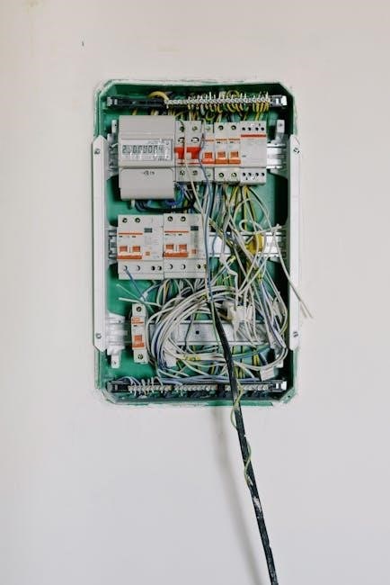
A 3-way dimmer switch contains physical components like the dimming dial and on/off switch‚ as well as electrical elements such as resistors‚ capacitors‚ and a microprocessor to regulate lighting levels smoothly.
Physical Components and Their Functions
The physical components of a 3-way dimmer switch include the switch itself‚ the dimming control mechanism‚ and the wiring terminals. The switch typically features a slider or dial for adjusting brightness‚ while the terminals connect to the electrical circuit. Key parts include the on/off toggle and the dimmer knob‚ which regulates light intensity. The housing protects internal electronics‚ ensuring durability and safety. Some models may also have an LED indicator to show the switch’s status. These components work together to provide precise control over lighting levels‚ making them essential for efficient and convenient operation.
Electrical Components and Their Roles
The electrical components of a 3-way dimmer switch include wires‚ terminals‚ and internal circuitry. The wires consist of the line (hot)‚ load‚ and traveler wires‚ which connect the switch to the power source‚ light fixture‚ and other switches. The terminals provide secure connections for these wires‚ ensuring proper circuit flow. The dimming circuitry‚ such as triacs or MOSFETs‚ regulates the power supplied to the light‚ enabling brightness adjustment. Some switches also include a microcontroller for smart features like remote control or preset settings. These components work together to safely and efficiently control the lighting system‚ providing smooth dimming and reliable performance.
Safety Precautions for Wiring a 3-Way Dimmer Switch
Always turn off the power supply before starting any wiring work to prevent electric shocks or short circuits; Use a voltage tester to ensure no live wires are present. Never touch electrical components with bare hands or tools without proper insulation. Wear protective gear like gloves and safety glasses to minimize risks. Follow the wiring diagram carefully to avoid incorrect connections that could cause hazards.

General Safety Tips Before Starting the Installation
Before installing a 3-way dimmer switch‚ ensure the power is turned off at the main electrical panel or breaker box. Verify this using a voltage tester to avoid shocks. Never work on live circuits‚ as this poses serious safety risks. Wear insulated gloves and use tools with non-conductive handles to further protect yourself from accidental electrical contact. Ensure the work area is well-lit and free from water or moisture‚ as these conditions can increase the danger of electric shock. Always follow the manufacturer’s instructions and the wiring diagram provided with the dimmer switch. If you are unsure about any step‚ consult a licensed electrician to prevent potential hazards. Proper preparation and adherence to safety guidelines are crucial for a safe and successful installation.
Common Mistakes to Avoid During Wiring
One of the most common mistakes when wiring a 3-way dimmer switch is incorrectly identifying the load‚ line‚ and neutral wires. Always refer to the wiring diagram to ensure proper connections. Mixing up the traveler wires can lead to malfunctioning switches‚ so label them carefully during installation. Another mistake is forgetting to turn off the power at the circuit breaker‚ which can result in electrical shocks or damage. Never assume the circuit is de-energized without verifying with a voltage tester. Additionally‚ using the wrong gauge or type of wire can cause inefficiency or safety hazards. Overcrowding the electrical box is another error‚ as it can lead to heat buildup and fire risks. Finally‚ not securing the wires properly with wire connectors can cause loose connections and unreliable operation. Taking the time to double-check each step and connection is essential for a safe and functional installation.

Step-by-Step Wiring Guide for a 3-Way Dimmer Switch

Follow a structured approach to install a 3-way dimmer switch‚ starting with preparing tools and materials‚ then connecting wires according to the wiring diagram‚ and testing the setup for proper functionality.
Preparing for the Installation Process
Before starting‚ gather necessary tools like screwdrivers‚ wire strippers‚ and a voltage tester. Switch off the power at the electrical panel and verify with a voltage tester that no electricity flows through the wires. Identify the line‚ neutral‚ and ground wires‚ typically colored black‚ white‚ and copper‚ respectively. Consult the wiring diagram to understand terminal connections: common‚ traveler‚ and ground terminals. Label wires to avoid confusion and ensure the dimmer switch’s rating matches the total wattage of the lights. Verify bulb compatibility with the dimmer switch‚ as not all bulbs are dimmable. Plan the wiring setup with a sketch to visualize connections and ensure compatibility with any paired 3-way switches. Secure all wire connections firmly to prevent issues like flickering or overheating. Proper preparation ensures a safe and successful installation.
Connecting the Wires to the Dimmer Switch
Begin by attaching the ground wire to the dimmer’s grounding terminal for safety. Connect the line (hot) wire to the “common” terminal‚ ensuring it powers the switch. The traveler wires‚ typically from the second location‚ are connected to the remaining terminals. Follow the wiring diagram to match the correct terminals. Twist and cap any unused wires. Secure all connections tightly to prevent electrical issues like arcing or fire hazards. Double-check the wiring to ensure no cross-connections‚ which could cause malfunctions. Once connected‚ restore power and test the dimmer function across all switches. Proper wire connection ensures smooth operation and prevents potential hazards‚ making it crucial to follow the manufacturer’s instructions and wiring diagram accurately. This step is critical for reliable and safe dimming performance in a 3-way setup.
Troubleshooting Common Issues
Flickering lights or non-responsive switches often indicate loose connections or incorrect wiring. Consult the wiring diagram to verify all connections are secure and properly matched. Addressing these issues promptly ensures optimal performance and safety.
Identifying and Diagnosing Wiring Problems

When troubleshooting a 3-way dimmer switch‚ start by reviewing the wiring diagram to ensure all connections are correct. Common issues include reversed live and load wires‚ causing the dimmer to malfunction. Check for loose connections‚ as they can lead to intermittent operation or complete loss of control. Use a multimeter to verify voltage at the switch terminals and ensure proper continuity between wires. If the dimmer fails to control the light‚ inspect the wiring between the switches to confirm it matches the diagram. Incorrect wiring‚ such as connecting the traveler wires improperly‚ can prevent the dimmer from functioning correctly. Always turn off the power at the circuit breaker before inspecting or repairing any wiring to ensure safety. Consult the wiring diagram frequently to cross-reference your setup and identify any discrepancies that may be causing the issue.
Fixing Common Issues with the Dimmer Switch
Common issues with a 3-way dimmer switch often stem from improper wiring or faulty components. If the dimmer fails to control the light‚ check the wiring diagram to ensure the live‚ load‚ and traveler wires are correctly connected. A frequent problem is the reversed connection of the live and load wires‚ which can prevent the dimmer from functioning. Additionally‚ verify that the dimmer switch is rated for the type and wattage of the connected light bulbs‚ as exceeding the capacity can cause malfunction or damage. If the dimmer hums or overheats‚ inspect for loose connections or overloaded circuits. In some cases‚ the dimmer switch itself may be faulty and require replacement. Always refer to the wiring diagram to ensure all connections match the manufacturer’s specifications‚ and test the system gradually to identify and resolve issues systematically.
